OpenModelica
OpenModelica is an open-source Modelica-based modeling and simulation environment intended for industrial and academic usage.
Installation of OpenModelica
The models shown below were created by using OMEdit v1.16.
Using a Linux OS, sometimes may lead to problems while trying to install OpenModelica. In this case, try to download the pre-built virtual machine.
Mac users are strongly encouraged to run OpenModelica as well as the OMG toolbox in a Linux VM.
Creating Microgrids with OpenModelica
The microgrids are created with a user defined library. To start it, run the file grid.mo directly in the folder omg_grid.
This package contains all components and required for creating the power electronics driven microgrids, as well as some example networks.
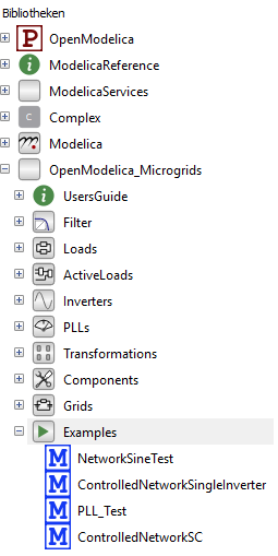
It contains several folders with predefined components, filters, loads etc. as well as microgrids for the FMU export to Python and some stand-alone examples which can be run directly in OpenModelica.
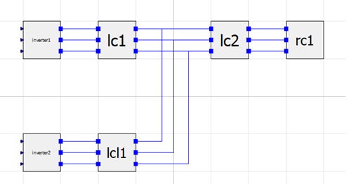
Main components of any microgrid are the three-phase inverters. They consist of three input voltages controlled by a cascaded PI-PI controller in Python. Default nomenclature for those inputs is i1p1 for “inverter 1 phase 1” etc, but it can be changed in the python code (model_input=[‘one’, ‘two’,…] in the env=gym.make() call).
Important: By using filters/loads with inductors or capacitors, leave the checkbox for the initialization in the provided settings. Changes are likely to result in errors while creating the FMU or running the Python files.
The provided examples are designed for up to two inverters, but the underlying models can be easily extended in order to investigate on more complex microgrid topologies. Extended example showcases are also planed for future releases.
Power Losses
In the default example “network”, no power losses in the inverters or filters are included. For the latter they can be added by using parts out of the “Filter.LossesFilter” package instead of the “Filter.IdealFilter” package. Due to a big increase of components and equations in the ODE-system, the simulation time will increase. For modeling losses inside the power electronic converters, adding a model in the Python interface scripts is recommending. Integrating, e.g switching losses, directly in the OpenModelia model will require to reduce to simulation step size significantly.
For larger simulations with a demand of power loss modeling, it is recommended to create user defined filters with only the resistors which are needed for the calculation. To modify them, create a new package (ctrl+N, specialization: package), duplicate the part which is to modify in the new package (right-click on it, duplicate, select the previously created package in path) and modify it there.
Switches / Transistors
Modeling switching-like events inside the model, e.g. triggering loadsteps by adding or removing loads, is desirable, but difficult to implement with the possibilities of OpenModelica. Switches in OpenModelica - like in many other free modelling languages - are designed as resistors. A closed switch has a low resistance, an open switch a high one. “Removed” loads are still connected to the grid. Connections with resistors in such dimension cause numerical issues while simulating as the ODE system becomes stiff. There are solvers available for stiff equation systems like BDF and Radau or ones with automatic stiffness detection, but using the switches often runs into non-converging systems and execution errors.
The working alternative is a parameter-variation of the load. It is possible to change the parameters of any load during a simulation and apply loadsteps in this way (see the topic Python code).
Setting of v_DC
The DC supply voltage v_DC can be set either directly in the OpenModelica model or via Python. In the OM model, doubleclick in your network on the inverter, and change the parameter v_ DC to the demanded value. All three phases of the inverter will be supplied with the same DC voltage. The default value is 1000 V. The default value can be changed with a right-click on an inverter, open class, select text view on the top left corner of the model canvas, and change the number in the following code line to the demanded default value:
parameter Real v_DC = 1000;
Phase-Locked Loop (PLL)
The PLL blocks are working for simulations in OpenModelica, but out of structural reasons, the PLL is calculated in Python.