Two Inverter Static Droop Control
In this example, a FMU generated by OpenModelica as gym environment containing two inverters, each connected via a filter to supply in parallel a RC load is used which is shown in the figure below. This example uses the controllers as defined in the auxiliaries. One inverter is set up as voltage forming inverter with a direct droop controller which e.g. frequency drops due to the applied power. The other controller is used as current sourcing inverter with an inverse droop controller which reacts on the frequency and voltage change due to its droop control parameters by a power/reactive power change. In the default settings, plots of the abc signal as well as the dq0 signals of the master and slave are provided.
By default, the following small network will be simulated:

A short introduction to experimental controller tuning with some hints can be found here.
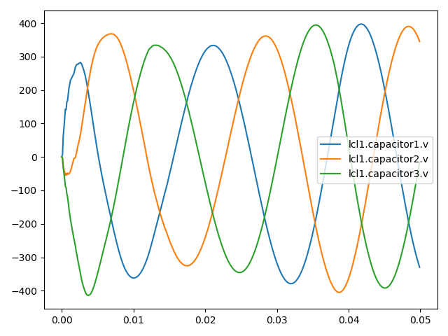
If the controller works fine, a three phase voltage similar to the following one should be one of the plots.

Any other demanded signal which is provided by the FMU or saved during the simulating can be plotted by adding it to
viz_cols=['*.m[dq0]', 'slave.freq', 'lcl1.*'],
in the gym.make() command. Make sure that demanded signal from the fmu are listed as a model_output:
model_output={
                   'lc1': [
                       ['inductor1.i', 'inductor2.i', 'inductor3.i'],
                       ['capacitor1.v', 'capacitor2.v', 'capacitor3.v']],
                   'rl1': [f'inductor{i}.i' for i in range(1, 4)],
                   'lcl1':
                       [['inductor1.i', 'inductor2.i', 'inductor3.i'],
                        ['capacitor1.v', 'capacitor2.v', 'capacitor3.v']]},
                   )
Hint: Every possible variable which is provided by the FMU can be seen the easiest in OpenModelica. Run the simulation without input signals, so every result for voltages and currents should be 0. On the bottom right side, you can select each component of the model in the tree structure. Clicking through the components until reaching the variable will show the whole variable name (for example lcl2.inductor2.i) on top of the plotting window.
The parameters of the controller like the control frequency delta_t, the voltage, frequency or droop characteristics can be set directly in the main function.